ARTIST NAME:
  William J. Beaty

TYPE:
  Kinetic sculpture; animated computer/gas-discharge cellular
  automaton  (see MPEG 930K)

DIMENSIONS:
  Wall-mounted, somewhat flat, attaches to a wall at the top,
  approx 4ft vertical, 12 ft wide, 4in thick, w/wall-mounted
  power supplies below.

MATERIALS:
   Cellular automaton algorithm, parallel microcomputer array, Tesla coils,
   adhesive foil electrodes, gas-discharge tubes, sinewave generator,
   power supply

INTERACTION:
  Motions of gallery visitors are detected and used to slowly modulate
  the sinewave generator, adding randomness to the slow wave motion of
  the lighted plasma.  The thermal infrared sensor is located centrally
  below the lower edge.  To avoid the impression of "electric eye"
  control, the sensor ignores any fast waving of hands, but responds
  strongly to the moving warm bodies of strolling visitors.  Future
  change: use the sensor to trigger a propagating wave, as if a stone
  has been dropped into the "water."

GALLERY REQUIREMENTS:
  As with a broad horizontal painting, it's wall mounted at approximately
  chest height.  It requires a 120Vac outlet of only a couple of amps.
  The fluorescent tubes do not light nearly to full brightness, so the
  dynamic glow effects will be not be visible in a brightly lit gallery.
  The tubes run at around one watt each, so it won't need an entirely
  dark room, but also it cannot be placed next to white walls with
  intense floodlights.  (I can provide one glowing tube and we can test
  the amount of ambient light which is appropriate.


STATEMENT:
  If "Art is the lie that makes us realize the truth," then art contains
  far too much lying; far too much of the shallow facade of technical
  expertise (or with luck, too much of shallow surface esthetics.)  No
  matter the acclaim directed at certain works, usually we detect nothing
  beneath their surface besides our own psychological projections.  The
  Quality within a piece depends almost entirely on the perceiver, and
  most art is one-dimensional in this way.  But is it even POSSIBLE to
  create Quality which is separate from the Quality projected by a human
  audience?  Let's find out.  My goal is to attack the universal trend of
  art based on shallow facades and viewer-provided interpretation.

  The "Pond Machine" series attempts to expose the deep and multi-level
  esthetics concealed behind the mundane face of the material world.  The
  series is focused upon a single element in nature: the nature of water.
  I then explore various ideas and phenomena by presenting distorted but
  active embodiments of the hidden physics and mathematics of fluids in
  order to make these ideas and phenomona directly visible, or better yet,
  directly grasped.  Rather than the well-explored "art as Rorschach-blot,"
  call it "art as chemistry-set."


CONTACT:
  William Beaty
  PO Box 351700
  Seattle, WA 98195-1700


  http://amasci.com/art/pondmach/pond3.html
This is an Open Source device
Below is the detailed tech information for those wishing to harness the
same effect for use in their own work.
Pond Machine III uses standard 4-ft fluorescent tubes, but runs them in
"plasma finger" mode. Each tube is driven by a two-watt miniature Tesla
coil device. These are the
Five-dollar Tesla Coil
available from several electronic surplus companies.
If we connect the high-voltage terminal of this Tesla coil to one end of
a fluorescent tube, then apply the required 5volt DC power supply, the
tube lights up. No Ground connection is needed, since the high frequency
AC
creates a virtual return path to ground through the space around the
tube. This particular type of Tesla coil gives proportional
output voltage, so if the DC power supply is varied between 0.9V and 5V,
we can smoothly control the brightness of the tube. At the low end of
the power supply voltage, a "plasma finger" effect is seen, where the
plasma first ignites at the tube electrode, then it grows longer as
the Tesla Coil output is increased. However, the brightness of the
"finger" is very low, and it extends the full length of the tube long
before the DC supply is cranked up to the full 5 volts.
The plasma-finger brightness can be easily increased by bringing a
grounded metal plate near the tube, but this also shortens its length,
and the DC power supply voltage must be increased to preserve the same
length but at higher brightness. Brightness is also limited by the 2-watt
Tesla coil output. To tailor the plasma-finger length to the drive
wattage, I replaced the metal ground plate with an adhesive foil strip
3/16-in in width, adhering this strip along the length of the tube and
connecting the far end of the strip to a Ground connection. The
plasma-finger length is not totally proportional to DC power supply
voltage, but the nonlinearity can be removed by using a long triangular
ground foil: starting at 1/4" wide at the HV end, and tapering to 1/8"
wide at the far end of the tube. If you use tubes of a different type or
different length, you'll probably need a foil strip of a different width.
(And for applications where all sides of the tube must be visible,
replace the adhesive foil strip with hair-fine magnet wire wrapped in a
loose spiral around the glass tube.)
My first prototypes used 40-watt four-foot fluorescent tubes. I soon
found that the common and inexpensive tubes of the 34-watt or EW
"environwatt" type DON'T WORK!. They contain a different gas mixture
than the older 40-watt tubes, and they require a much higher voltage than
these tiny Tesla Coils can provide. The older 40-watt tubes remain
available, but they cost twice or more than the "EW" types.
The original "III" version shown at Seattle COCA
gallery used a direct connection between the Tesla Coil output and
one pin of the fluorescent tube filament. I found that this was a bad
idea, since driving the plasma at a high voltage with an unheated
tungsten filament causes a metal-sputtering effect which slowly destroys
the internal electrode and sprays unsightly dark metal onto the
fluorescent coating at one end of the tube. (Lightning engineers call
this drive method "sledge-hammering", and rapid blackening of the tube
ends are the well known result.)
In version "III.i" I switched over to Nikola-Tesla electrodless drive
method to avoid the black contamination. The early history of
fluorescent tube lighting is unknown to most people:
gas-discharge tubes were popular playthings during the era of Victorian
science, but then near the turn of the century the American inventor
Nikola
Tesla harnessed them to light his laboratory in NYC, later showing them
off as part of the Westinghouse exhibit in the 1893 World's Fair in
Chicago. Tesla's flourescent lamps used no hot filaments as today's do,
but instead
were either lit wirelessly using the intense e-field from a nearby radio
transmitter (Tesla Coil,) or they used a metal electrode wrapped around
the outside of the glass at one end of the tube. This method is known as
"electrodeless discharge" or "RF light source."
There is no filament to fail and no problems with black metal-dust
contamination, so
tubes powered in this way could theoretically last forever.
The foil electrode has a minimum size. The value of high voltage from
this particular Tesla coil determines the minimum value of series
capacitance between the plasma and the metal sheet outside the glass, and
that determines the area of the foil. I found experimentally that the
minimum area of adhesive foil needed for an outside contact was one
square inch. I used a couple of square inches of 1" wide copper foil
adhered to the tube (locating it a couple of inches from the end, so that
the plasma cloud doesn't touch the metal internal parts and cause
blackening.)
The microcomputers of course did not directly supply the 300mA 5-volt
drive signals for the tesla coils. I used power FETs, one per tesla
coil, soldering the pins directly to each small PCB. I used type IRL530
FETs from Digi-key (with a 2.0v
turnon threshold,) open-drain circuit, then added 1.8 ohms in the source
leg to give a limited gain for more linear response. To allow 100Hz PWM
drive input I added a 4.7uF tant cap in parallel with the FET Gate
terminal and a 68K in series between the computer and the gate. To allow
adjustments to compensate for the different FET's gate threshold voltage
I added a trimmer network consisting of a 33K from Gate to ground, and a
100K trimmer pot from Gate to +5V DC supply, with a 56K in series with
each 100K trimpot. This allows a smooth change between 0 and 5VDC, low
current signal, to control the drive current of each Tesla coil between 0
and
300mA.
![[thumbnail of above photo, starts MPEG video]](http://amasci.com/art/pondmach/pndthb.jpg)
![[flash photo from the front, of the 84 close-packed vertical fluorescent tubes]](http://amasci.com/art/pondmach/pflsfrsm.jpg)
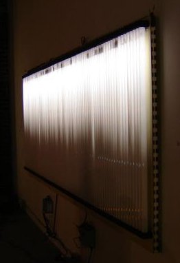
![[Larger oblique photo of the glowing tubes. The region of glow in each tube is a different length. It looks like glowing upside-down grass. But it moves!]](http://amasci.com/art/pondmach/Pnsid2sm.jpg)
![[Longshot of wall-mounted Pond Machine, other kinetic
sculptures in foreground: crawling glowing finger robot, happygrass
computer]](http://amasci.com/art/pondmach/DarkAsm.jpg)