ELECTRONIC
SURPLUS
CATALOGS
The Big List
INEXPENSIVE FET ELECTROMETER ARRAY
1994 William Beaty, Museum of
Science, Boston
The schematic depicts the basic 'cell' of the Inexpensive Visual
Electrometer Array. The MPF102 is a Field Effect Transistor available
from Radio Shack and many other places. Any LED will do, but diffuse
wide-angle, high-brightness types like MV5753 (Active Electronics) are
best. Screws with nylon insulators were used in the panel. With a
1-in. wire antenna,
the circuit is small enough to be built atop a 9-volt battery clip, then
used as a handheld probe. With a 24-in. wire antenna, the circuit is
sensitive enough to respond to the waving of a charged comb or balloon
/across the room.
In the present circuit, the LED turns on when a positive charge approaches
the antenna, and turns off when negative charge approaches. The 1-meg
resistor limits spark current should any large, charged persons actually
touch the gate wire.
The earth-ground point in the circuit can actually be at any of the
schematic nodes, not just the one shown. And if the circuit is
battery-powered, you can even ground the gate and use the entire circuit
and battery as the "antenna." I use the point shown in the schematic
because it allows the handheld version to easily be lit/darkened via the
battery: Hold the gate lead, touch one battery terminal, then release the
gate lead. Depending on the + or - terminal you touch, the LED goes on or
off.
While extremely inexpensive, this particular circuit has a problem.
It can be turned on and off! In other words, it suffers from inductive
charging via the diode junction which is part of the FET gate, and this
makes the circuit behave differently with positive signals than with
negative. If a negative charge approaches, the LED turns off, and when
the charge is removed, the LED turns on. The opposite is NOT true for
positive charges. If a positive charge approaches and the LED is on, the
LED will stay on, but the FET's internal diode will turn on and allow the
gate wire to become charged. When the positive charge is removed, the LED
will turn off and stay off! There is a "memory" effect involved with the
circuit, and so the circuit does not always reflect the state of the
e-fields in the space around it. However, it is amazing that such a simple
device detects e-fields at all, and the price is so low that every student
can have their own e-field sensor. For hard numerical data, an expensive
electrometer instrument can be used instead. If you are building a much
smaller array, you might want to consider using a FET input opamp circuit
and red/green polarity indicator LEDs.
THE ARRAY ELECTROMETER
To protect the circuit from direct discharges, I placed a 10meg resistor
in series with the lead wire coming from each antenna screw, and I
connected an NE-2 neon pilot light between the FET gate and earth ground.
The glass of the neon bulbs turned out to cause humidity problems
(decreased sensitivity) on moist days, so I painted the base of each bulb
near the lead wires with red-brown, high-voltage insulating spray paint.
It's important to not touch the base of the neon lamps either before or
after painting, since fingerprints become conductive when moist. Handle
them only by the lead wires. If there are finger prints on them, scrub
them off in a bowl of rubbing alcohol.
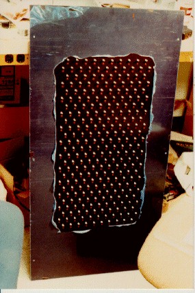
For the main panel I used sheet aluminum anodized with black color (which
I picked because the black wasn't insulating,) bought from a decorative
metal supplier. It was covered by a peel-off protective sheet which is
seen in the JPEG image (and must be removed when complete.) If you use
another material for the plate, be aware that if the panel is coated with
a good
insulator such as paint, it also becomes a good trap for ionized air, for
"frictional" charges, etc. It invariably will become charged up and
distort the light patterns terribly.
You might wish to experiment
with
placing the whole panel behind glass. This will protect it from direct
discharges, but if the glass becomes charged (will there be fur or cloth
provided?), the exhibit will go flakey on you. The conductive panel is
connected to earth ground.
Each "antenna" screw was next to an LED. The screws were 6-32, and
stuck out about 3/8" from the panel. I think I used 3/4" screws, to give
adequate length out the back. I used black "socket cap" screws just to
keep everything black for good contrast. The vertical rows of sensors
were about 1" apart, the screws were about 1.7" spaced vertically, with
each LED about 3/4" from each screw. I bought white nylon insulators from
an electronics catalog (digikey.com.) One of the insulators was of the
screw-insulator
type, it was like a 6-32 shoulder washer, but with a little thin tube
sticking out
of the side. The other insulator was an 8-32 unthreaded nylon spacer 3/8"
long. The two insulators meshed together with a slip-fit action, which
totally isolates the screw from touching the grounded metal panel. Drill
each hole with a #16 bit. The
6-32 washer is mounted from the rear of the panel, the 8-32 washer is
placed over it
from the front,
the screw is inserted from the front, then the nut and solder-lug are
screwed on
the back.
Keep the nylon parts very clean. Don't open their bags
until
you're ready and install them while wearing gloves. If the washers get
any salty fingerprint contamination on them, they can become conductive on
humid days. If one or more segments stop working on humid days, it means
that surface contamination is somewhere present on the washers, on the
NE-2 bulb, or even on the FET itself.
To power the array I first soldered each FET to its adjacent LED, to the
antenna lug, and to the NE-2 bulb. This leaves each element with two
disconnected leads, a positive and a negative. I used horizontal wires to
connect each row of elements together in parallel (I stripped small holes
in the insulation to allow solder connection.) These wires are visible in
the photo above: yellow for positive, bare wire for negative. Then I
attached long thin pieces of copper circuit board vertically to the
aluminum panel, then soldered all the horizontal wires to the circuit
board strips.
Here's an advanced feature for the ambitious designer. I figured out how to reset the whole array so the LEDs would all dimly glow. I connected each antenna-screw to a 15pF 200V capacitor, all going to a common bus. I found that if I raised this bus voltage to 150VDC, then lowered it to zero, then any pattern on the array would be wiped out. Note that it might be possible to damage the FETs if you SUDDENLY connect this array to -150VDC and then to ground. So, I used relay switching of resistors and capacitors to slowly charge the array to -150V in about 0.1 second, then discharge it again in about 0.1 second. Such a slow change will keep the gate currents low and prevent transistor burnout. A pushbutton and a timer circuit runs the relay sequence.